Connection Erectability Settings
- Step-By-Step
- Tips and Tricks
- Related Tools
Use oversize holes in beam moment flange plates:  or
or  .
.
If this box is checked (
If this box is not checked (
Stability angle section size: Any angle section (angle) that is listed in the local shape file. The angle is used when the Stability angle for a beam seat is set to Field bolted and its Location is set to On flange.
To enter an angle: You can type in the section size that you want, or you can press the file cabinet browse button
( and double-click a section from the list of available sizes. The angle you enter here must exist in the local shape file, or validation does not accept your entry.)
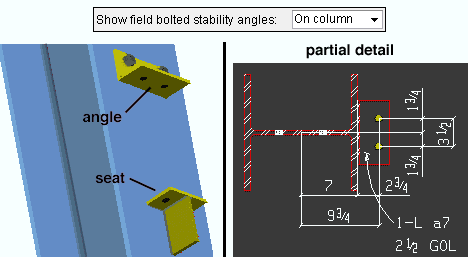
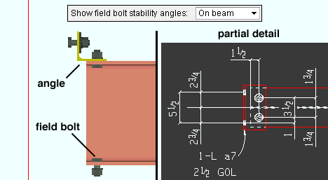
Show field bolted stability angles: On column or On beam or Ship loose. The selection made here applies to selected beams with seated beam connections and also to beams with safety erection angles applied to the Top flange.
On column sets the angle to be shop-attached to the column (and therefore detailed with the column).
On beam designates that the angle be bolted to the beam in the shop and that it therefore should appear on the detail of the beam.
If Ship loose is selected, then for seated beam connections a stability angle is not designed by connection design and will not appear on details for either the column or the beam. For a safety erection seat added to a clip angle, bent plate, end plate or shear connection, Ship loose shop bolts the safety erection angle to the column.
Maximum amount of allowable k infringement: The distance that bolted connection material is permitted to ride on the fillet of a wide flange or S shape or channel beam. This field may potentially affect the positioning of clip angles, bent plates, end plates, shear plates, and beam splices.
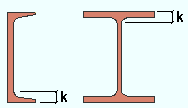
|
k = k distance. Allowable k infringement is the distance a material can overlap into this area. |
Effect on connection design: Connection design uses the beam's k distance (detail) (from the local shape file) to calculate the maximum amount of allowable k infringement. Connection design uses that calculated value unless it exceeds the value entered here. If the calculated value exceeds the value entered here, connection design uses the value entered here.
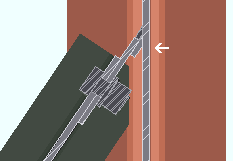
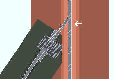
Use backing bar for pre-qualified welds: ![]() or . This applies to skewed beam-to-beam or beam-to-column shear tab connections with angles to the supported beam of less than 45 degrees. The views in the following illustrations are from below the top flanges of the beams. It applies when Use backing bar is set to Automatic under the shear
or . This applies to skewed beam-to-beam or beam-to-column shear tab connections with angles to the supported beam of less than 45 degrees. The views in the following illustrations are from below the top flanges of the beams. It applies when Use backing bar is set to Automatic under the shear ![]() Connection specifications
Connection specifications
|
|
If this box is checked (
If the box is not checked (
Do weld prep on moment flange plates: ![]() or
or ![]() . This applies to bolted moment connections whose flange plates have groove welds.
. This applies to bolted moment connections whose flange plates have groove welds.
|
|
If this box is checked (
If the box is not checked (
Safety erection seat options
Seat angle section size: Any angle section (angle) that is listed in the local shape file. The angle is used for the connection design of a safety erection seat when ![]() Use a safety erection seat is checked under the
Use a safety erection seat is checked under the ![]() Connection type
Connection type
To enter an angle: You can type in the section size that you want, or you can press the file cabinet browse button
( and double-click a section from the list of available sizes. The angle you enter here must exist in the local shape file, have a minimum leg of 4" (or 100 mm), and have a thickness of 1/4" (or 6 mm); otherwise, validation will not accept your entry.Note: If the connection to the supporting member is Bolted, there may not be sufficient entering and tightening clearances for bolts, even when the Seat angle section size exceeds the minimum size accepted by validation. In that case, the connection will fail with the message Bolt gage not within reqd min/max values.
Safety erection seat connection to supporting: ![]() Bolted or
Bolted or ![]() Welded. This setup option applies to the connection design of a safety erection seat when its Attachment is set to Automatic under the
Welded. This setup option applies to the connection design of a safety erection seat when its Attachment is set to Automatic under the ![]() Connection type
Connection type
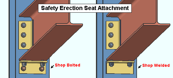
Bolted instructs connection design to shop bolt the safety erection seat to the column.
Attach long leg to: Supported or Supporting. This applies if the entered Seat angle section size has legs of unequal length; in that case, you can decide which member the long leg is attached to.
Supported field attaches the long leg of the angle to the supported beam.
Supporting shop attaches the long leg of the angle to the supporting column.
Gage on leg to supported member: The distance from the heel of the angle to the center of the row of holes on the leg that bolts to the supported beam.
Note: Connection design may apply a different GOL than the one you entered, depending on the bolt size, the angle material's allowable entering and tightening clearances, and its minimum edge distance.
Gage on leg to supporting member: The distance from the outside corner of the angle to the center of the row of holes on the leg that bolts or welds to the supporting column.
Note: Connection design may apply a different GOL than the one you entered, depending on the bolt size, the angle material's allowable entering and tightening clearances, and its minimum edge distance.
Gap for safety seat on bottom flange: The distance of the gap between the safety erection seat and the bottom flange of the supported beam. This applies when Location of safety erection seat is set to Bottom and Auto is checked for Safety erection seat gap on the Beam Edit window for the supported beam.
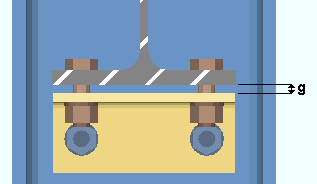
|
g = gap between the safety seat and the bottom flange of the beam. |
Bolt detailing options
Bolt diameter: The diameter of the bolt to which the other bolt detailing options are applied. For each bolt diameter, bolt row Spacing is applied, and a Tension controlled tool type (Large or Small) is selected. Entering and tightening distances are also entered for each diameter. Bolt diameters that are listed here are commonly recognized imperial and metric bolt sizes.
Controlling bolt diameters on connections can be done using the NM bolt type to supported and NM bolt type to supporting (beams), NM bolt diameter (columns), NM bolt diameter (vertical braces), and NM bolt diameter (horizontal braces). The bolt diameter that is used in the connection then sets the row spacing per the bolt Spacing values that are entered here.
Be aware that connection design may automatically increment bolts on beam connections and columns splices. To permit connection design to automatically increment bolts to any of these sizes when designing shear plates, clip angles, bent plates, end plates, beam splices and column splices, you should make sure that these sizes are checked on the Available bolt diameters setup list. Connection design does not increment bolts on vertical brace or horizontal brace connections.
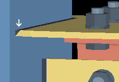
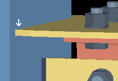
Spacing: For each Bolt diameter that is selected, this option sets the distance between rows of bolts in a system connection.
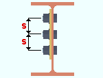
Bolt spacing is the distance between any two adjacent rows of bolts in a connection. A single-plate shear connection is shown in this example. 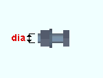
When connection design attempts to create a connection for a particular bolt diameter, it applies the bolt spacing for that bolt diameter, which is entered here. Effect on connection design: The bolt spacing values entered here apply to connection design on members that subsequently undergo Process and Create Solids. Spacings potentially affect the positioning of holes on virtually all system connections, with the exception of base/cap plates and moment end plates.
Example: You get the end connection failure message Beam not deep enough for connection for a shear plate connection that you have entered. To fix this problem, you manually type in a NM bolt type to supported that is larger than any of the bolt sizes that are on the Available bolt diameters setup list. Connection design is able to generate a shear plate connection with the desired bolt diameter. Since you entered a large-diameter bolt, the vertical spacing between rows of bolts on the shear tab are adjusted according to the entry made here, for that bolt size.
Also see: Top of Steel to First Hole.
Tension controlled tool type: Large or Small. The type of impact wrench to be used in the field to enter and tighten tension control (TC) bolts of the selected Bolt diameter. The tension control tool type applies to that diameter when a TC bolt is selected for a connection. For example, the selected tool type will apply when a TC bolt is selected as the NM bolt type to supported or the NM bolt type to supporting under the ![]() Connection type
Connection type
Large instructs connection design to use the Large tensioned controlled tool settings to determine which clearances are acceptable for the selected Bolt diameter.
Small instructs connection design to use the Small tensioned controlled tool to determine which clearances are acceptable for the selected Bolt diameter.
Default settings to the... tensioned controlled tool options for each bolt diameter use values suited to North American or European erection practices, depending on which Connection design method you selected when you created your current Job.
If your tools are sized differently than those assumed by the default settings: You can change entries to the C1, C2, and C3 fields of the Large tensioned controlled tool and Small tensioned controlled tool options to accommodate the actual dimensions of your impact wrenches.
Non-tension controlled tool: The entering and tightening clearance distances for conventional high-strength bolts of the selected Bolt diameter. The non-tension controlled tool settings apply to bolts of that diameter when a non-TC bolt is selected for a connection. For example, they apply when a non-TC bolt is selected as the NM bolt type to supported or the NM bolt type to supporting under the ![]() Connection type
Connection type
| Entering and Tightening Clearances | |
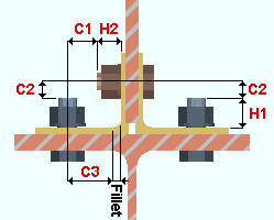
|
H1 = height of head H2 = maximum shank extension (based on one standard washer) C1 = clearances for tightening C2 = clearance for entering C3 = clearance for fillet, circular only (based on one standard washer) |
Default settings to these fields for each bolt diameter use values suited to North American or European erection practices and tool diameters, depending on which Connection design method you selected when you created the job. The settings may be updated to accommodate the actual dimensions of your impact wrench. Refer to the illustration above for the distances entered in these fields.
Large tension controlled tool: The entering and tightening clearance distances for tension control bolts of the selected Bolt diameter when the Tension controlled tool type is set to Large.
| Entering and Tightening Clearances | |
|
|
H1 = height of head H2 = maximum shank extension (based on one standard washer) C1 = clearances for tightening C2 = clearance for entering C3 = clearance for fillet (based on one standard washer) |
Default settings to these fields for each bolt diameter use values suited to North American or European erection practices and tool diameters, depending on which Connection design method you selected when you created the job. These settings may be updated to accommodate the actual dimensions of your impact wrench. Refer to the illustration above for the distances entered in these fields.
Small tension controlled tool: The entering and tightening clearance distances for tension control bolts of the selected Bolt diameter when the Tension controlled tool type is set to Small.
| Entering and Tightening Clearances | |
|
|
H1 = height of head H2 = maximum shank extension (based on one standard washer) C1 = clearances for tightening C2 = clearance for entering C3 = clearance for fillet (based on one standard washer) |
Default settings to these fields for each bolt diameter use values suited to North American or European erection practices and tool diameters, depending on which Connection design method you selected when you created the job. These settings may be updated to accommodate the actual dimensions of your impact wrench. Refer to the illustration above for the distances entered in these fields.


|
|
OK (or the Enter key) closes this screen and applies the settings.
Cancel (or the Esc key) closes this screen without saving any changes.
Reset undoes all changes made to this screen since you first opened it. The screen remains open.
- Settings applied to the Connection Erectability Settings screen are for your current Fabricator. A different set of settings will apply when you Change Fabricator.
- Red or yellow exclamation point icons
 or
or 

